Facebook Pixel

Siemens VMP42.10(2) 1/2" 2-Way Valve Assembly 0.47 Cv

Special Price $157.68 Regular Price $181.34
In stock
SKU
VMP42.10(2)
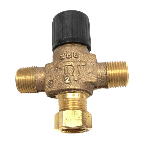
Siemens VMP42.10(2) is a 1/2" 3-way valve assembly offering high efficiency for precise control in HVAC systems. Engineered to provide a flow efficiency of this valve is designed for efficient fluid flow management in heating and cooling applications.The valve is designed to work with a 2/10Vdc modulating control signal for smooth, accurate adjustments to meet system requirements. With a 3 way design it can control the flow through of water or some other fluid directing it to different paths depending on the system's need for lubrication. Its versatility however makes it fit for use both in small and large scale HVAC systems where exact fluid management is required.
https://www.partshnc.com/media/catalog/product/v/m/vmp42-10-2_1.jpg

Specifications

  • Valve Type: 3-Way
  • Size: 1/2"
  • Flow Efficient: 0.47Cv
  • Dimensions: 4" x 5.3" x 3"
  • Weight: 1.02lbs
Manufacturer Name: Siemens Building Technology
Product Number: VMP42.10(2)
OEM Part Number: VMP42.10(2)
Product Description: 1/2" .47Cv 2Or3w Vlv Use W/Ssc
Weight:1.02lbs/462.66g

Choose the best HVAC equipment parts and supplies from PartsHnC!

  • Same Day Shipping

  • Best Quality And Best Price

  • Wide Range of Inventory

  • Best Customer Service

Have More Questions or Need Help to Place The Order?
Reach us at (866)773-0907 or [email protected]

Write Your Own Review
You're reviewing:Siemens VMP42.10(2) 1/2" 2-Way Valve Assembly 0.47 Cv
Your Rating
Customer Questions
What maintenance is required for the Siemens VMP42.10(2) Valve Assembly?

Regularly inspect the valve assembly for leaks, corrosion, or sticking components during operation. Clean external surfaces and ensure actuator movement remains smooth. Check all fittings and seals for tightness to prevent pressure loss and maintain secure, efficient system performance.

What are common issues with the Siemens VMP42.10(2) Valve Assembly?

  • Leakage at valve body or connection points.
  • Sticking or restricted valve movement.
  • Actuator failure causing improper control.
  • Internal wear reducing flow regulation accuracy.
  • Seal degradation leading to pressure instability.

Installation Steps

Step 1: Safely isolate power and fluid supply before starting and verify zero pressure.

Step 2: Close upstream isolation valves completely.

Step 3: Clean pipe ends thoroughly and remove debris.

Step 4: Align valve with flow direction arrow correctly.

Step 5: Apply thread sealant and connect fittings securely.

Step 6: Tighten to manufacturer torque specification and wear gloves.

Step 7: Restore system flow gradually and test for leaks carefully.