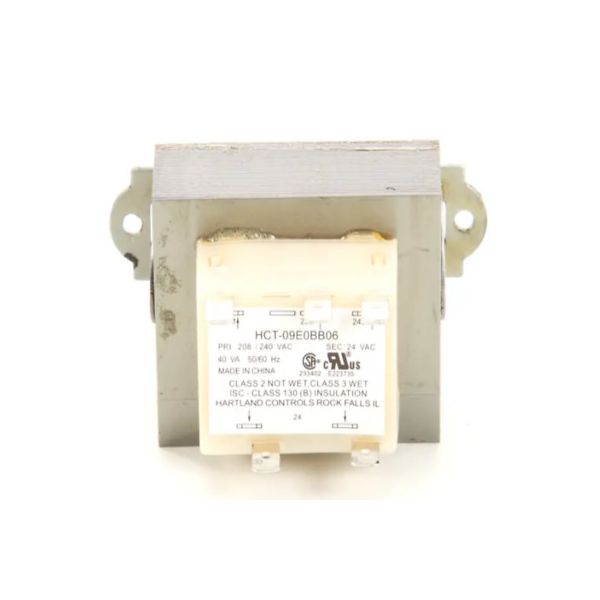
Hartland Controls HCT-09E0BB06 Class-2 Transformer 208/240V PRI 24V SEC
Special Price $42.32 Regular Price $55.02
In stock
SKU
HCT-09E0BB06

The Hartland Controls HCT-09E0BB06 Class-2 Transformer is a control power component that is part of an HVAC system to transform 208/240 V primary voltage into 24 V secondary voltage to supply low-voltage circuits. The mounting will be done in the control compartment of the equipment, where primary and secondary leads will be attached to the respective wiring terminals. This transformer can assist in the provision of a dependable supply of control voltage to allow the system controls and safety equipment to operate uniformly.
Manufacturer: