Facebook Pixel

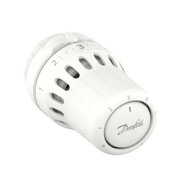
Danfoss 015G3098 Thermostatic Sensor Mounted RAS-D

Special Price $77.76 Regular Price $89.43
Out of stock
SKU
015G3098
The Danfoss 015G3098 Thermostatic Sensor Mounted is a temperature sensing component used in radiator control assemblies to regulate heat output based on room conditions. It responds to temperature variations by expanding or contracting its sensing element which influences valve movement for controlled flow adjustment. In HVAC systems it is mounted directly on compatible radiator valves to ensure accurate temperature detection at the heating point. It supports balanced heat distribution, maintains stable indoor comfort levels, and contributes to efficient thermal regulation through precise sensing and responsive control action.
https://www.partshnc.com/media/catalog/product/0/1/015g3098.jpg

Specifications

  • Type: Thermostatic sensor
    Write Your Own Review
    You're reviewing:Danfoss 015G3098 Thermostatic Sensor Mounted RAS-D
    Your Rating
    Customer Questions
    What maintenance is required for the Danfoss 015G3098 Thermostatic Sensor?

    Regularly inspect the sensor for dirt, corrosion, or loose connections. Ensure it is securely mounted and the sensing bulb is properly positioned. Clean surrounding components to prevent interference. Proper maintenance ensures accurate temperature regulation and system efficiency.

    What are common issues with the Danfoss 015G3098 Thermostatic Sensor?

    • Delayed or sluggish temperature response.
    • Erratic system cycling or control fluctuations.
    • Electrical connection faults causing intermittent operation.
    • Sensing bulb damage reducing accuracy.

    Installation Steps

    Step 1: Turn off power to the refrigeration or HVAC system before starting.

    Step 2: Select a suitable location on the suction line for the sensor.

    Step 3: Mount the new sensor securely using the provided bracket or clamps.

    Step 4: Attach the sensing bulb to the line, ensuring good thermal contact.

    Step 5: Connect the sensor wires to the control unit according to the wiring diagram.

    Step 6: Restore power and verify proper temperature sensing and system operation.