Facebook Pixel

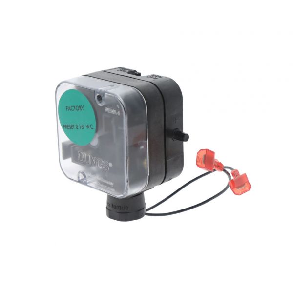
AERCO Boiler and Water Heater 60011-4 Blower Proof Switch Assembly

Special Price $525.02 Regular Price $582.77
In stock
SKU
60011-4
The AERCO Boiler and Water Heater 60011-4 Blower Proof Switch Assembly is a safety monitoring system that is installed in commercial boiler and HVAC systems. It is mainly used to ensure that the combustion blower is running and that it is supplying sufficient airflow before ignition of the burner. This mechanism works by a pressure-sensing switch that reacts to the changes in the airflow created by the blower and provides a confirmation signal to the control circuit. The installation is made in the blower or combustion air assembly, where it is connected to the control wiring. The switching unit promotes the correct sequencing of ignition.

https://www.partshnc.com/media/catalog/product/6/0/60011-4.jpg

Specifications

  • Type: Blower Proof Switch Assembly
    Write Your Own Review
    You're reviewing:AERCO Boiler and Water Heater 60011-4 Blower Proof Switch Assembly
    Your Rating
    Customer Questions
    What maintenance is required for the AERCO 60011-4 Proof Switch Assembly?

    Regularly inspect the switch for dust, corrosion, or loose wiring connections. Ensure the blower and surrounding components are clean and unobstructed. Proper maintenance ensures accurate detection of blower operation and prevents unsafe burner conditions.

    What are common issues with the AERCO 60011-4 Proof Switch Assembly?

    • Switch failing to detect blower operation.
    • False trips or frequent shutdowns.
    • Corrosion or buildup affecting contacts.
    • Intermittent electrical connectivity or signal issues.

    Installation Steps

    Step 1: Turn off all power and fuel supply to the boiler before starting.

    Step 2: Remove the access panel to locate the existing blower proof switch.

    Step 3: Disconnect the wiring from the old switch, noting terminal connections.

    Step 4: Mount the new switch assembly securely in place.

    Step 5: Reconnect all wires according to the original configuration.

    Step 6: Replace the access panel, restore power and fuel, and test the system for proper operation.